|
X1-01- Lamp Clamp
As I was making tool holders for my C3 QCTP I got a bit over-enthusiastic with one of them and accidentöly made a too wide dove tail. What to do? Throw away, no but it may make a good work light holder for the bench mill.
A smallish project and this for the bench mill for a change. A faulty bit to be turned into something useful in a new surrounding. It will become a lamp clamp for the mill.
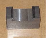
Bild 1: The faulty tool holder
Yes, split the tool holder in two, add a couple of guide pins and a lock screw down the center. That will make a good clamp to fit the dove tail of the column. A small angle att one end to act as holder for the goose neck light will do the rest. I use n IKEA Jansjo goose neck lamp here. Its little "foot" is just perfect for this thing.
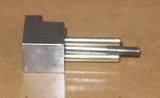
Bild 2: The split tool holder
At this stasge the tool holder is drilled and split, has got two guide pins and the lock screw is in place. Next is the angle to which the lamp is fitted. I want the angle rounded so that it follows the lamp foot.
A bit of round bar with a 6 mm hole down its center will be the center of rotation. To avoid the whole contraption rotating I milled out a pair if recesses and drillaed and threaded a small hole right beside the center peg and with the same diameter. The hole was then used for a short stop screw to prevent the round bar from ratating during the milling and it worked very well.
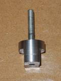 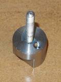 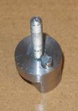
Bild 3-5: Center of rotation
The ready center as shown above. When the milling was done, the extra stop screw was removed and the lamp angle was mounted and secured with a nyloc nut.
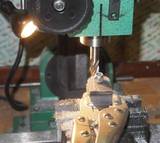
Bild 6: Ready for milling
I held the lamp angle with a sterady grip and a lockable welding pliers and rounded the angle off very easily. When the milling was done the un-necessary bit was sawn off and the angle finished to measure in the mill.
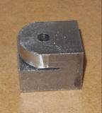
Bild 7: The now rounded angle.
The angle fitted the clamp very well and a lock nut was required. I did not want just a knurled nut as I find easy to slip with oily fingers so I made three little pegs instead.
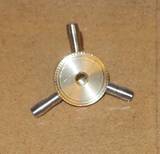
Bild 8: The lock nut.
A trial assembly to make sure everything fits. It does and looks as below.
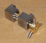
Bild 9: Assembled without lamp.
At this point the angle is fitted to the opposite side of the lock nut, but only using a screw in its center. It is enough as the angle gets some support from the column dovetail and cannot rotate. I choose to mount the foot of the lamp so that the cable is turned towards the column. That will make it easier to guide it away from anything to catch. The trial assembly below shows that it works. (Better picture will come.)
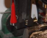
Bild 10: Fitted to the left side of the column.
As the goose neck is quite long on this IKEA light it is easy to get into an angle where it gives a good light on the job. The light comes from a high power LED with good light and low power consumption. By using only one screw to secure the angle to the clamp it is easy to fit the whole thing to the right side of the column as well.
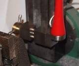
Bild 11: Fitted to the right side of the column.
The clamp is loosened and turned 180 degrees then re-locked. The clamp can now be fittedto the right side instead and this makes it possible to get the light whereever is fits best and works best.
This proves that it is not always necessary to throw bits away, in this case it wound up as a very useful acccessory with a great deal of flexibility.
Further Development
Having got this far with the clamp I realized that it may be of even more use.
Having a fixed point on the mill for mounting indicators or cooling fluids spouts is really a bonus. By changing the angle lock screw for a bar which is both a lock screw and an 8 mm fixed bar, it is possible to get this new function as well. The angle lock screw would then look like this.
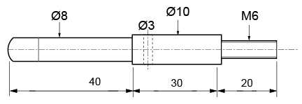
Skiss 1: The new lock screw with its 8 mm bar.
I choose 8 mm as that is the dimension the rest of my measuring accessories use.
Even More Developments
An un-planned session in the workshop made it possible to complete the accessory by making the new screw according to the sketch. It turned out that the M6 part should ponly be 17 mm long, and the cross hole to be 4 mm diameter, but in all other respects the measures are correct.
Done and re-fitted it looks as above from the right side ...
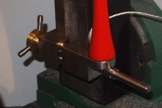
Bild 12: Lamp and clamp on the right side.
... and like this from the left.
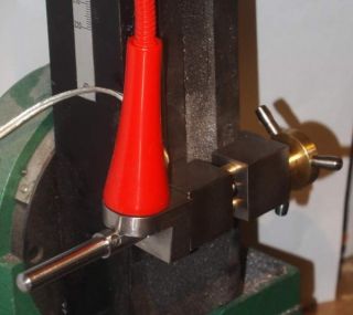
Bild 13: Lamp and clamp to the left.
With this the new accessory is completed and ready for use in every way.
|