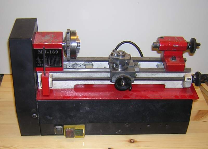
I had some suitable material on hand in the form of a nice bit of 1 mm sheet steel. It was sawn to measure and folded. Then got some holes to suit the ones in the motor casing as shown below.

The 10 mm wide edge on front, back and to the right were folded in 45 degree angle . The fold to the left is 90 degrees to fit closely to the drive belt plate at the headstock. All for a good fit.
Following a trial fitting the swarf tray was sanded, cleaned and the corners were filled with epoxy glue to becomer more stable and enable smoothing without sharp corners. Then a couple of coats of paint, this time red to fit the machine.

The trial fitting showed that it was necessary to enlarge the fixing holes between the drive belt plate and the headstock about 1 mm upwards to compensate for the tray thickness. The holes are the two to the right of the large vertical opening.

With that done, the tray was fitted between the machine feet and the motor casing. The screws were secured, and heureka, the machine has now got a swarf tray that looks as it had been there all the time.

IT is really quite odd that there were no swarf tray from the beginning, but this little project solved the det6ail and gave me a better machine as a result. Now smallish parts does not fall of and hide anymore, and the swarf stays in the tray.